The AR94 speaker system is the least expensive model in the early ‘80s Teledyne AR 9x line of speakers that is headed by the massive (and sought after) AR9. The AR94Sx version may have been the ‘price leader’ within the 94 model designation – at least the woofer and woofer/midrange drivers are the flimsiest.
I have wondered if the mediocre performance of the Sx (mostly in the midrange, most noticeable with vocals) is responsible for the relatively low regard (and selling price) the AR94 gets in the marketplace. At least there are a lot of them available, and the price is right. Whether or not you go with foam surrounds instead of rubber, and copper wire for the tweeters instead of silver, and inexpensive polypropylene capacitors instead of his choices is very much up to you. There is no real design change here, just replacing old parts. He certainly is enthusiastic about the sound he ends up with. I tried this crossover in the 94Sx; it doesn’t work – nasty sounds in the midrange. If you do get AR94Sx speakers (they seem to be pretty common out there) there still may be hope; here’s the story.
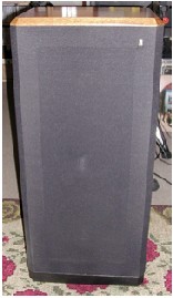
Photo #1 – The AR94Sx
First things first – getting the sock out of the way
- Tip the speaker upside down on a clean rug. Four screws hold the base on; their heads take a #2 Philips screwdriver.
- With the base removed you can see the staples holding the sock. I use a common screwdriver and pliers to remove them.
- Now you can peel and push the sock down the sides of the speaker, past the tweeter.
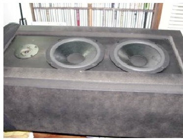
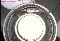
Photo #2 – a peeled speaker
The Opening
Lay the speaker on its back. The drivers are held in place by ‘deep thread’ wood screws; use that #2 Philips screwdriver on them. Pull each driver out far enough to get at the wire connections – the wires will have crimp-on terminals from the factory. I used a red Sharpie to mark the terminal of the positive wire. You may wish to mark the woofer or the woofer/mid to avoid mixing them up, though in the Sx version they are identical. Pull the polyester fiberfill from each box and (if you are doing this at that time of year) stash it where cluster-flies won’t drop into it.
New surrounds?
The original surrounds for the 8” drivers were foam. If they haven’t been replaced, they are rotted. Replacements are available from several sellers on eBay, and several retailers elsewhere. I got mine from Parts Express. Theirs come with instructions for the job.
Note that the PE kit contains four surrounds, of two different configurations. One of those configurations is right for these drivers, the other will work, but it’s harder to install and won’t look as ‘professional’; get two kits. Also note that, because the spider is quite stiff, it holds the cone centered around the voice coil well; you don’t need to disturb the screen-type dust caps.
I recommend that you do the surrounds now rather than later, because if you wait to do them last irresistible haste could set in.
It’s an easy enough job, but not if you’re in a hurry.
The Tweeter
This 1-1/2” cone tweeter is common to several Teledyne AR speaker models. It is referred to with respect for its sound quality by AR-philes, but is found in the blown state pretty often (I blame rockers used to horn-loaded towers). Finding the dust cap pushed in is common. There are several methods for pulling the cap back into shape, none of them guaranteed. Because this driver is a cone-type rather than a dome-type, I’m not convinced that the dented cap has any significant effect on driver output.
I have seen mention of a new replacement tweeter for about $50 (while reading posts at AudioKarma), but don’t know the source. Finding one used and unblown may not be easy. If you are not a ‘stickler for stock’, the Dayton 1-1/8” silk dome tweeter (part #DC28F-8) is inexpensive and should do the job sonically, but it isn’t a drop-in fit. You’ll have to make the mounting hole bigger.
Now to the nitty-gritty – the crossover
First you have to get it out of the box. I used a 1” wooden dowel and a hammer to beat it out. The fiberboard probably won’t come out cleanly; there will be some bits of it and maybe a staple or two to dig out afterward. The crossover pc board will be intact.
The Sx version crossover is different from the one that TNT article deals with. We know that one doesn’t work with this speaker, so that’s no surprise.
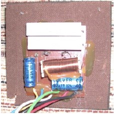
Photo #3 – the stock xover
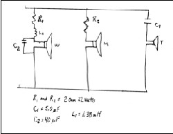
Photo #4 – schematic of stock xover
Lots of glue there. Note the iron core inductor; circuit designers prefer air core inductors now, so we’ll go along with them. We are going to reuse the resistors and the connecting wires though. I clipped the wires and the resistor leads next to the pc board; there’s enough resistor lead left to work with. You can gain a little by melting the solder connections, but you have to get the resistor freed from the glue before the solder hardens again….
Designing the new crossover
I failed to locate any of the specs for these drivers. If I had found them my competence to use them is definitely marginal; so, a lot of guessing took place. It’s highly unlikely that my component choices are the best ones.
There’s no point in designing anything without having a notion. My notion was that the unrestrained midrange driver is clashing with the tweeter. I know that the AR engineer had a reason for not putting a low-pass filter there, and he had to be a better engineer than I am, but nuts to all that; I’m going to limit how high the midrange goes, and change how low the tweeter goes.
My thinking is that the mid/woofer crossover should be quite a bit lower than 3KHz with this 8” cone, so the tweeter crossover has to come down some to avoid a dip in system output. These are 1st order filters though (6dB/ octave), so maybe the starting points don’t need to be the same. I measured the DC resistance across each driver coil, made guesses about impedance in each case, and used the ‘loudspeaker calculator’ available at www.mhsoft.nl to find values for 1) an inductor that starts filtering at around 1900Hz with a driver of 7 Ohms impedance and 2) a capacitor that starts filtering at about 2500Hz with a driver of 8 Ohms impedance.
I suspect that lowering the crossover point for the tweeter makes it even more susceptible to overload and failure. If you listen to music at high sound levels you maybe ought to change the woofer/mid crossover to 2500Hz or so, and leave the tweeter crossover at 3KHz. I didn’t intend to change the woofer crossover, but the closest value I found for the inductor is 1.40mH instead of the original 1.38, and the closest capacitor value 47 microFarads instead of 40. So this crossover point is a little lower than stock.
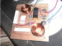
Photo #5 – the new xover
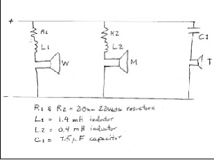 Photo #6 schematic for new xover
Note that the schematic doesn’t show the 47 microFarad capacitor that bridges the woofer coil. That’s because I placed it at the woofer instead of on the crossover network board. I probably should show it on the schematic, but then you’d be looking for it on the board and muttering.
The crossover board is ¼” plywood, 5-1/2” x 6”. As you can see, there’s plenty of room there. There’s plenty of space in the bottom of the speaker box too. I drilled a clearance hole in each corner of the board for a #8 x ¾” screw, and two 5/16” holes in the middle for the ‘5-way’ binding posts. When you install the posts use a star washer on each side of the board to keep the post from turning when you hook up the interconnects. Glue the other components to the board using an adhesive that won’t attack them. An adhesive that smells like vinegar probably isn’t good. I used Ace All-Purpose Adhesive; there are several other choices.
I used dimes as solder pads, to anchor wires which otherwise could wander around and connect to something they aren’t supposed to. Note that I used solderless terminals on the negative wire ends, but soldered them to the wires anyway. Those solderless terminals on the driver end of the wires are prone to breaking off; might as well replace them now.
Reassembly
I guess it’s obvious that the crossover board goes in first. Make sure that the speaker bottom doesn’t have any bits of old fiberboard remaining to get in the way; this is supposed to be a sealed box. Put the stuffing in next, getting it as evenly distributed as you can. Connect the wires to each driver before it goes into the box – it’s easier to be sure the polarity is right. Make very sure that the tweeter wires are the ones you are connecting to the tweeter.
You need to run a bead of sealer around the outside edge of the crossover board (n the base), and let it cure before powering up.
Tests
I tried to be scientific during this crossover project.
First I replaced the old caps with new ones in one speaker, and compared the sound with that of the ‘unrenewed’ speaker. There was a little improvement, but not much.
Next I built and installed a ‘TNT’ version crossover in the second speaker, and compared its sound with the speaker having the
‘renewed’ crossover. The ‘TNT’ version was much worse; something unpleasant going on in the midrange. This crossover and the Sx are not a good combination.
The crossover we just finished is the one I tried next, comparing it with the speaker still having the renewed original crossover. The test music: 1) a soprano singing arias with orchestra backing and 2) Mozart’s clarinet concerto. The music does sound better. I can’t tell if it really sounds good until both speakers are finished and in a reasonable listening environment.
Conclusions
As you may have guessed (otherwise why would I write this article?) the speakers do sound good in a ‘reasonable listening environment’. I think they are well worth the approximately $200 I’ve invested in them – plus I had fun tinkering with them. I see two questions though, both unanswerable by me:
- How much of this improvement in sound is a psychological reaction by me – the tinkerer?
- If the improvement is real, why didn’t the AR engineers do it this way?
If you try this project you may find the answers. Have fun with it.
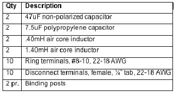
Parts List (not including possible new surrounds)
QtyDescription Materials