No one would argue these are not interesting times. One of the tiny benefits of times as interesting as these is that there are a lot of great web sites that will guide you through the process of making your own speaker cables, power cords, and interconnects. I have used some of those sites in the past while experimenting with making my own cables and I recommend them as a great staring point. This article is intended to be a next step in DIY wire assembly.
When it comes to your audio system everything makes a difference. I’m sorry to just blurt that out, but it had to be said. If you are of the mind that wires can’t, and therefore don’t, make a difference then you have my envy. You may consider this article a parody and hopefully you can enjoy it as such. What do you do when you hit upon a simple easy way to make great sounding interconnect cables? If you are me, you try to figure out how to make a superior connector to plug them into.
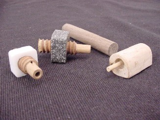
 When I started making my own Female RCA connectors there were no pure silver connectors on the market. I had recently transformed my system using all solid core, single strand, pure silver wire with remarkable results. I noticed that there was no place in the system where the replacement of copper with silver had not been met with thunderous applause from…well, me. If the wires made that much of a difference than it stood to reason the connectors at either end of the wires had to make a difference too, possible even more of a difference. With inspiration from companies like 47 Labs and Eichmann, I made my own Male RCA connectors from hard woods. I bought ½” hard wood dowels in various species to experiment with. After cutting the dowels to length, I drilled a 5/16” hole in the center of one end about 3/8” deep. This forms the outer or grounding part of the connector. To make the positive or signal part of the connector, drill a 1/8” hole ¼” deep in the center of the first hole. This allows the insertion of either a ½” length of 1/8” wood dowel or a ½” length of hollow plastic tubing. The tubing I used is recycled from the ink tubes in the cheapest BIC pens. If you go with the 1/8” wood dowel it will need a very small hole to be drilled through it to fit the wire through. This process requires quality tools and lots of patience and provides limited benefits. I recommend the plastic tubes.
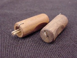
The last step to the male RCA connectors involves drilling two small holes through the connector to allow the wires to enter from the back. These holes are just slightly bigger than the silver wire itself. I attached the finished wood connectors to both ends of my single strand, 28 gauge, Teflon insulated, fine silver, one twist per inch, 3 foot long wires. The wires can be sealed at the connectors with hot melt glue or hot wax if needed.

The resulting interconnects were a real eyeopener. I had made an interconnect that eliminated all solder joints. The singularity and minimizing of metals was clearly an audible bonus. They simply sounded like nothing. I was inspired to go further.

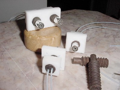
My first attempts at making panel mount connectors involved using fine silver sheet and a Teflon body. Before this version could even be tested version 1.01 was underway. In order to eliminate any solder joints in the signal path I decided to redesign the connector.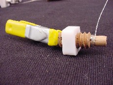
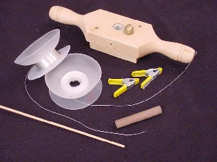
Starting with ½” hard wood dowels and a ½” threading kit, available at fine woodworking stores near you or on the net, thread the entire 3’ dowel and cut it into as many 2” long pieces as you need. Using a center finder made for lathe work, mark the center of both ends of all the pieces. Drill a 1/16” hole straight through the center of the threaded pieces. Without removing the piece from the drill bit use the drill as a lathe to spin the threaded 2” long connector. Wrapping a 5/8” wide block of wood with sand paper will make it easy to grind the threads off of the last 5/8” from the end of the threaded piece. Grind the end that is closest to the drill for stability. When the threads are gone you need to be careful to go slowly till you get to the finished dimension of the pin. Slightly taper the pin toward the end away from the threads.
This is the pin you will wrap the wire around for the ground/return part of the connector. From the pin end drill a hole just slightly bigger than the wire running lengthwise through the body of the connector. Be careful not to drill into the threads. Take a 36” length of wire and feed about half of it (18”) through this hole. Use a clamp to secure the wire where it protrudes out of the rear of the connector. While holding tension on the wire with a gloved hand, to protect you from the heat, tightly wrapped the wire carefully around the pin form as far as you are able. The pin will be a little longer than the finished length at this time and we will trim it to length at the end. While keeping tension run a very small amount of silver solder around the wound wire. If properly done you will still be able to see the individual turns of wire but the coil will be one solid piece. When the coil is cool trim the excess wire.
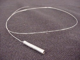
To make the return or signal part of the connector you will need a three foot long 1/8” dowel and second 36” length of wire. A vise is very handy for this step. Starting at the mid point of the wire, wrap the wire around the dowel tightly keeping tension on both ends. When you have a 1” long coil use silver solder to make the coil solid. The dowel will be ruined in the process. When the coil is cool break it off the dowel. While holding the coil very carefully with a pair of pliers, drill out the center of the coil with a 1/8” drill bit. This will remove the dowel and solder from the inside and provide a smooth silver contact surface. Drill a 3/16” hole 5/8” deep into the center of the pin where there is a 1/16” hole currently. Thread the wire through the center hole and tap the coil into place. Trim the pin with a hack saw to ½” long.
Use very fine sand paper on the negative or return coil to smooth it and remove any solder. Protect and insulate the wires with Teflon spaghetti tubing. The threading kit comes with a tap, which will allow you to thread the nuts needed to attach the connectors, or if you are installing the connectors in a wood cased component you can just thread the wood case and screw in the connectors.
The threading kit has other audio uses. I have replaced the steel bolts holding toroidal transformers with wood ones. I also use the threaded dowels as speaker wire clamps. Everyplace I have replaced metal with wood and eliminated solder in the signal path has made a positive change. Give it a try.
Hello,
If it isn’t too much trouble I would like some close up pictures of the inside. I am planning on making some rca plus out of HDPE dowels. I have concerns about the durability though.
-Anthony