Nearly all vintage pre-amps/integrated amps have headphone jacks. Unfortunately some of them don’t work, or stop working. Also unfortunately, some of these jacks are hard to get at, and some are directly mounted to the main PC board or one of its satellites (meaning you have to match its configuration in a catalog. Building a headphone amp from a kit is actually an easier “fix”. It is also known that some audiophiliacs favor separate headphone amps for reasons that may not be psychosomatic, but this amp, the Ramsey model #SHA1, isn’t audiophile class. I’ve been browsing an audiophile class catalog (from Acoustic Sounds Inc.) and didn’t notice anything electronic in there for around $30, which is what the SHA1 goes for. (If you haven’t seen this catalog, I recommend it; there are some amazing things in it – including some strange looking turntables and the prices are even more amazing.) This amp sounds decent supplying my Sennheiser 595 phones. There are a few caveats, but I’ll get to them later.

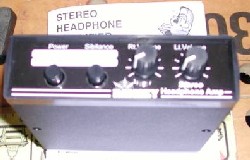
Photo #1 – In the wrapper
Just so you don’t get overconfident, Ramsey puts the PC board on top. Yep, all those things you see outlined there have to be soldered in place. Really, it isn’t difficult; the instructions are mostly very clear and the layout isn’t tight. Um, there are a few little things, but I’ll point them out to you.
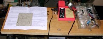
Photo #2 – The work area
The deal here is organization and room to work. The kit parts are in the divided container on the right that used to hold ‘stakons’. You don’t need the fancy soldering station, but I have one and it’s nice. Besides what you see here you need solder – ‘skinny’ solder, I think it’s .018 caliber. You can use thicker solder, .032 or so, for anchoring the switches and jacks. And you’ll need dikes (diagonal sidecutting pliers) and probably needle-nose pliers.
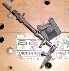
Photo #3 – The work holder (aka “third hand”)
You don’t have to have one of these, but if you aren’t equipped with three hands (you’ve got the soldering pencil in one, the solder in another…). I’m not going to tell you how to solder, or show you; there are tutorials all over the place that do that better than I can. I’ll just add that a big thing when soldering components onto a circuit board is to use enough solder but not too much. That’s the reason for using skinny solder.
Static control
The instruction manual doesn’t mention static electricity, and if your work area ‘climate’ is reasonably humid you probably don’t need to be concerned about it. If the air is dry, as it usually is indoors in winter and in places like Arizona all the time, you need to ground yourself and the work surface, because the LM386 ICs won’t tolerate static. The voltage regulating transistor may not like it either. I have an antistatic wrist strap and work area pad, both grounded to house ground at the same point.
Following Directions
The kit includes a ‘parts list updated 04/27/06 use this list’. Use it to make sure that the kit contains what the list says it does – and have the list handy when you start assembling. The instruction manual didn’t get updated when the parts list did. The assembly instructions for the PC board are clear and complete; just do what you’re told – with the following exceptions:
Steps 2 & 3
– use the .001 uf capacitors here (as identified in the updated parts list).
Steps 4 & 5
– use the 390K ohm resistors (orange-white-yellow) listed in the updated parts list. An installation tip: these resistors go onto/into the board easier if you bend the leads parallel with each other first, close to the resistor body.
Steps 11 & 18
– there’s nothing wrong with the instructions, but I have to tell you that I installed IC sockets here. I have this paranoia about cooking the innards of the IC while messing around with the soldering pencil – and if I want to replace the chip later (a better performer could come out anytime, y’know) it’s a lot easier to do with sockets. There’s a knack to installing ICs without bending over (and sometimes breaking – aargh) pins. First make sure the pins are in line on both sides; on a new IC they probably will be. Also on a new IC, the distance between the lines of pins will be a little greater than the holes they go into; this is a good thing. Next, start one row of pins into their holes; not far, just enough so they’ll stay in there. Then tip the chip so the other line of pins is just above the holes. Gently squeeze the line of pins so that they line up with the holes, and insert them. When all pins are where they belong, push the chip down to the board (or socket) surface. With a little practice this procedure is much easier than I’ve made it seem.
Step 26
– This says to “Install C1, the remaining 10uf electrolytic capacitor.” This rattled me, because I knew I had two more of those capacitors in the tray. They get installed in steps 35 & 37, so all is well. A few soldering notes: In several places where two soldering points are close together you may be alarmed to see the solder run between them. This is usually because the points are connected in the foil – so it’s OK. The solder points for the 10uf capacitors are pretty close together too, but you don’t want to bridge those. The pins for the DPDT switches are close together, but the solder behaves itself – if you don’t use too much; use that skinny solder.
The case
The instruction manual doesn’t tell you how to get the board mounted in the case, but near as I can tell there’s only one way it will work.
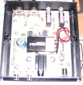
Photo #4 – The board in the box
- Set the board on the mounting posts (in the half of the case that has mounting posts), but don’t put in the screws yet.
- Tip the board up at the front (switches) end, place the front plate over the switch shafts, and slide the plate into the grooves in the case.
- Push the board toward the front of the case, so you have room to mount the back plate in the case grooves.
- Now install the screws to fix the board to its mounting posts.
- Install the case bottom. Note that the mounting screws aren’t quite central on the case; if the screws drop all the way down, you need to turn the case bottom around. The kit contains four pads to stick on the case bottom.
Photo 5 – The (slightly fuzzy) finished product
Operating tests
I can’t call this section ‘listening tests’, because my ears are old and tired, and refuse to register anything above 9KHz. This is why I don’t volunteer to audition system components, Mr. Editor. The sound that I hear through this amp is OK by me.
Testing equipment:
- Sennheiser 595 headphones;
- AudioSource model Pre One/A preamp;
- Pioneer DV-250 DVD/CD player;
- Philips “walkman” style portable CD player; a classical (orchestral) CD.
- The Ramsey amp is powered by the 9 volt battery.
- There is a pretty loud pop through the headphones when the amp power switch is pressed. This occurs whether or not the amp is connected to a music source. There is a lesser pop when the switch is turned off. None of these pops are loud enough to harm phones or hearing, but they may well be annoying to the easily annoyed.
- There is a moderately loud pop through the headphones when the ‘sibilance’ switch is pressed the first time. Subsequent actuations produce little or no noise.
- There is a ‘situation’ with gain. With the amp connected to the ‘tape out’ jacks of the preamp, the signal to the Ramsey is much too strong. The amp’s volume pots must remain near zero level, and adjustment acts way too coarse for reasonable control. On the other hand, when the amp is connected to the portable CD player, I can set the amp’s pots to 12 o’clock and a comfortable listening level is reached with the player’s volume control somewhere around midrange. The same results are likely when a tape deck is the source – provided that the deck has an output volume pot. If I wanted to disconnect the preamp from the power amp I could use those jacks to supply the Ramsey; then the pre-amp’s volume pot would create a situation similar to other sources that have an output volume pot. I don’t consider this to be a reasonable solution though.
Conclusions:
As is, the Ramsey headphone amp is a useful way to drive relatively hard-to-drive high quality headphones when a portable CD player is the source. If the audio system you are using has no loudspeakers, and therefore needs no power amplifier, you can hear all of your music sources through a preamp/line source unit connected to the Ramsey, as long as that source has an output pot. If your intended use for the Ramsey is to make up for a missing phones jack in your preamp/integrated amp/ receiver, and you are connecting the Ramsey to the tape out jacks, then a couple resistors in the LM386 connection circuitry need to be changed, to reduce the gain. As a marginally competent DIY guy, I can’t determine which resistors or the value needed. Somebody at Ramsey knows.
That’s it, folks. Hope your part of the world has been getting more sun than my corner has been lately.